This is my entry for the fifth edition of The Giant’s Shoulders, to be held at Podblack Blog on November 15th.
By the late 1800s, physicists had begun a serious study of the structure of the atom. The best tool for such studies, indeed pretty much the only tool in that pre-quantum era, was a spectroscopic analysis of the light emitted/absorbed by the atom. Each species of atom radiates light at its own distinct, discrete set of frequencies (‘spectral lines’), and knowledge of these frequencies could be used, for instance, by astronomers to determine the chemical composition of distant stars.
Devices which could be used to analyze the spectral content of a light field in that era were, however, limited. Like a far-sighted person trying unaided to read the fine print of a newspaper, the spectroscopes of the time were limited in how well they could distinguish (‘resolve’) very closely-spaced spectral lines. Researchers needed a device which could outperform existing techniques, such as the use of a diffraction grating or a Michelson interferometer.
In 1897, Charles Fabry and Alfred Perot introduced a new interferometric device which would eventually bear their name: the Fabry-Perot interferometer. The design of the interferometer is, in principle, simplicity itself: light is passed through a pair of parallel, highly reflecting mirrors. Interference between components of the light undergoing multiple reflections result in extremely well-defined interference fringes emerging from the device, from which spectral properties of light can be deduced.
Fabry and Perot published a large number of papers on their interferometer, including 15 joint articles between 1896 and 1902. The first of these articles dealt with the theory of the interferometer and applied it to the accurate measurement of very small distances, while the second described the apparatus in detail and applied it to spectroscopy.
In this post, we discuss the scientists, their interferometer, the results of their first few papers, and the impact the F-P interferometer has had on physics in general.
The lives of Charles Fabry (1867-1945) and Alfred Perot (1863-1925) are rarely discussed1 in the physics world, unlike many other highly influential scientists. I tend to think that this is because they did not possess the eccentricities that make for good classroom anecdotes, like stories of Einstein, Feynman or Newton, for instance. They were ‘merely’ hard-working, exceptional researchers who had a great impact on the science of their day. Fabry was the theoretician of the two, and his doctoral work concerned the properties of interference fringes. The older scientist, Perot2, did his doctoral work in thermodynamics but then turned his attention to experiments in electromagnetic waves. In 1894 Fabry took over Perot’s position at the University of Marseille, while Perot went on to become a ‘Professor of Industrial Electricity’ at the same institution. This intersection marked the start of their collaboration, as well. Fabry handled the theoretical aspects of the interferometer, while Perot actually designed and built the device.
Their first paper on this subject3, published in 1897, described the theory of the interferometer, and applied that theory to the precision measurement of small distances between parallel metal surfaces. Their second paper4, which appeared in 1899, applies the interferometer to spectroscopy and gives detailed diagrams of the apparatus.
How does a Fabry-Perot interferometer work? Let us first hear it from Fabry and Perot themselves, from their first paper, (poorly) translated by me:
When one examines a thin slab of air by transmission using monochromatic light, ranging between two surfaces of glass, one obtains a system of fringes submerged in an intense uniform illumination.
…
The aspect of the phenomenon changes completely if the surfaces which limit the thin slab have a high reflection capacity. That occurs, in particular, when the thin slab lies between two surfaces of slightly silver plated glass, a slab which we will call simply a silver plated thin slab…
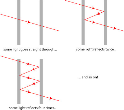
These fringes present moreover a very particular aspect in that on sees them in the form of very brilliant ones, separated by broad obscure intervals. This phenomenon is due to multiple reflections, which take a considerable importance when the reflection capacity is high; one then has to consider at the exit, in addition to the wave directly transmitted, the waves which emerge after undergoing 2,4,6,… reflections.
The highly reflective surfaces divide the wave into multiple parts; each contribution reflects an even number of times in the interferometer before exiting, as illustrated schematically below:
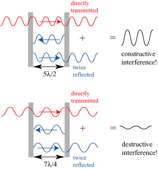
What happens when these different contributions emerge from the interferometer depends on the relationship between the size of the cavity and the wavelength of the light. For instance, if light of wavelength is normally incident on a F-P interferometer of length
, the different contributions will all emerge in phase if the cavity length is evenly divisible by a half-wavelength, i.e.
, where
is an integer.
In this case, we have constructive interference between the different components and the interferometer gives a strong light output. On the other hand, alternating contributions will cancel (destructively interfere) if the cavity length is evenly divisible into quarter-wavelengths, but not into half-wavelengths, i.e.
, where
is an integer.
These two cases are illustrated below. When the cavity is of length , ‘neighboring’ contributions all add up when they emerge from the interferometer, but when the cavity is of length
, ‘neighboring’ contributions will cancel. The overall effect is that the interferometer has a weak light output.
What happens if the light/cavity satisfy neither the constructive nor destructive interference conditions? For instance, suppose the cavity length is 15/16ths , a condition closer to constructive interference than destructive interference. Let us look at the how much successive contributions to the output field are delayed, in terms of wavelengths:
2 reflections: field delayed ;
4 reflections: field delayed ;
6 reflections: field delayed ;
8 reflections: field delayed = destructive interference!
Although the two-times reflected component of the field constructively interferes with the direct wave, the eight-times reflected component of the field destructively interferes with the direct wave! For any wave which does not exactly match the constructive interference condition, there will eventually be a reflected component which will cause destructive interference. Therefore, the F-P interferometer only transmits light under circumstances which closely match the constructive interference condition, provided the reflectivity of the mirrors is high.
We will not derive the theoretical results for the F-P interferometer, but they are worth listing. For an interferometer of reflectivity and transmittance
, and an optical field of wavenumber
and angle of incidence
, the intensity of the transmitted field may be written as
,
where is the input intensity of the field and
.
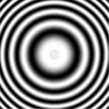
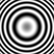
Because any optical field input into the interferometer will have contributions traveling in multiple directions (multiple angles ), the output of the interferometer will appear as a collection of bright, extremely narrow rings; a typical example is illustrated below:
The positions of the rings satisfy the condition
, where
is an integer.
To see why this is significant, let us compare this interference pattern to the analogous one produced by the Michelson interferometer, which was used for spectroscopy before the F-P device:
The fringes are much broader for the Michelson interferometer. We will see in a moment why this is a limitation for spectroscopic applications, but we first point out again the functioning of the Michelson interferometer:
In the Michelson interferometer, light is divided into two components, one of which is delayed by a distance , and the components are then interfered. In the F-P interferometer, light is divided into a large number of components, which are increasingly delayed by multiples of
. The sharpness of the F-P fringes are entirely due to the large number of reflections in the system.
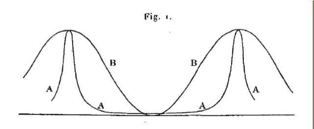
It would be remiss of me to not include F-P’s own comparison of the two sets of fringes:
The advantage of the F-P system for spectroscopy can be seen in the observation of fringes produced by two extremely closely spaced spectral lines. The 1897 F-P paper uses the two yellow radiations of a sodium salt, of wavelengths
and
.
The two lines are extremely closely spaced. If we were to filter the individual spectral lines and produce separate interference patterns, we would see:
:
:
If both lines are observed simultaneously, the interference pattern takes on the form:
Both spectral lines are clearly distinguishable! With the Michelson interferometer, the same pattern would take on the form:
There are still two separate interference patterns, but because of the broadness of the fringes, they overlap in a way such that they are indistinguishable. The F-P interferometer allowed the investigation of closely-spaced spectral lines which had previously been indistinguishable.
Here is the photograph of fringes that Fabry and Perot included in their first paper:
After describing the properties of the basic interferometer, Fabry and Perot applied their device to the precision measurement of the separation of reflective surfaces. To quote Fabry himself concerning the genesis of this application5,
The subject on which we began to work had occurred to me, partly by chance, following an observation in an electrical problem. A young physicist who was working with me wished to study the spark discharges passing between metallic surfaces separated by the very small space of a micron or less; he consulted me as to the method which he could employ to measure such small distances. I was already familiar with the phenomena of interference; and I thought at once that the interference methods would be the only ones capable of giving the required precision.
Fabry and Perot demonstrate in their article that one can observe colored interference fringes with a white light source if one uses two F-P interferometers in sequence. Their illustration of the setup is as follows:
Light is projected through one interferometer and the output is imaged onto the second. The result is a complicated colored interference pattern which depends upon the relative thicknesses of the two interferometers. The color of the interference pattern produced gives a ‘map’, of sorts, of the thickness difference. The research duo used a ‘prismatic’ interferometer as a thickness standard: a wedge of air of known thickness. By looking at the location on the prismatic F-P at which white light fringes appear, one can then determine the thickness of the reflective surfaces in question.
In their next paper, Fabry and Perot applied their new interferometric technique to the actual determination of the wavelengths emitted by a light source. We have seen above that, for a pair of closely-spaced spectral lines, one can use an F-P interferometer to clearly distinguish the two sets of fringes. However, it can be seen from the equation for destructive interference,
, where
is an integer,
that the position of the fringes depends on both the wavelength of light and the width of the interferometer. As the separation of the surfaces in the interferometer is increased, one will see the fringes move, and if two spectral lines are present, one will see the lines alternately separate and ‘melt’ together, as the following animation illustrates:
Don’t look at it too long, or you’ll get either hypnotized or sick! This simulation was performed for the two sodium lines described above, with reflectivity and the separation of the mirrors increasing from 100 microns to 400 microns.
Here’s where it gets interesting! Suppose we have two wavelengths of radiation in our source, and
. Now we increase the spacing of the interferometer until we find one set of fringes directly located between the other. Then it can be said that the light of the
th order fringe of the wavelength
has traveled a distance
farther than the light of the
th order fringe of wavelength
. One can quickly show that the ‘order’ of the interference fringe is directly related to difference in wavelengths, in the form
.
If we know the order of the fringe, which can in principle be determined from the separation of the mirrors, we can determine the relative separation in wavelengths. If we look at extremely high-order fringes, i.e. , we can determine differences as small as
!
To get fringes of such high order, one must have a separation between the mirrors of thousands of wavelengths. Such large, and adjustable, separations require a very carefully constructed device. In their second paper, F&P go into much detail about the device:
The two mirrors are at the top, labeled L and L’. The mirror L is designed to have very fast back-and-forth movement; it is affixed to a block of wood P which is free to slide on a plate of glass G. The mirrors must also be adjusted to be almost perfectly parallel, and both can be adjusted in angle, in order to bring them into parallel positions. I have to quote the paper on the means by which the angular adjustment of L is made:
Two small rubber bellows full of water support about the middle of the stem (T) via a bronze cube and tend to make it bend, one in the vertical direction, the other in the horizontal direction; each one of them communicates by a fine rubber tube with a tube with funnel and the whole is full of water. While varying the height of the funnels, one makes more or less bend the stem of steel and one obtains desired angular displacements.
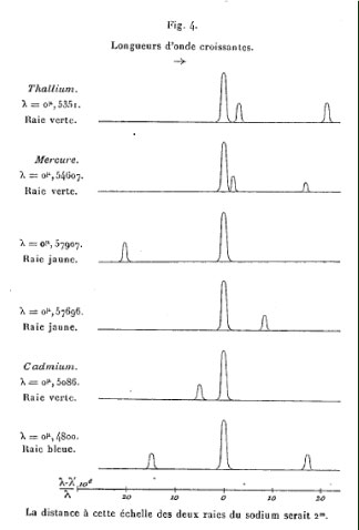
F&P applied their new interferometric apparatus to analyze the fine structure of the spectral lines of various metal vapors; they studied thallium, mercury, and cadmium; their results were illustrated as follows:
For many if not most of these lines, the F-P interferometric study was the first time they had been distinguished.
As we’ve said above, Fabry and Perot continued to elaborate on the uses of their interferometer, coming up with no less than 15 articles on the device and its applications! Other physicists quickly began to apply it in their own applications: they are still used for high precision spectroscopy experiments, and a Fabry-Perot-like cavity forms one of the principle components of a laser.
Fabry would not be constrained to simply playing around with his interferometer in later researches; in 1913, he discovered (with Henri Buisson) the Earth’s ozone layer. But that is a story for another time…
******************************
1 A useful reference which helped immensely in the preparation of this post is an article by Joseph F. Mulligan, “Who were Fabry and Pérot?” Am. J. Phys. 66 (1998), 797.
2 Perot was inconsistent in the spelling of his own name, sometimes using “Pérot” and sometimes “Perot”. In both papers I discuss here, his name is spelled “Perot”, so I stick with this spelling for my post.
3 C. Fabry and A. Perot, “Sur les franges des lames minces argentées et leur application a la mesure de petites épaisseurs d’air,” Ann. Chim. Phys. 12 (1897), 459.
4 C. Fabry and A. Perot, “Théorie et applications d’une nouvelle méthode de spectroscopie interférentielle,” Ann. Chim. Phys. 16 (1899), 115.
5 Fabry described this in his obituary of Perot in Astrophys. J. 64 (1926), 208. I quote it from Ref. [1] above.








Pingback: Let’s Read the Internet! Week 2 « Arcsecond
I love this, because it really gives you the sense of how groundbreaking this science was 100 years ago. Old science can seem fusty, but when you look back at the first-hand reports, it’s just as exciting as anything being done today.
That said, it’s probably easier to get that feeling about Fabry and Perot’s work since it ended up being on the main stream of science and is still in use today.
When I’ve read hundred-year-old books about things like aether theories, they’re much harder for me to interpret. I think it’s because many of the concepts they discuss didn’t stand the test of time, so there are fewer ideas in common between me and the authors.
Wade wrote: “Old science can seem fusty, but when you look back at the first-hand reports, it’s just as exciting as anything being done today.”
Agreed! There’s lots of interesting experimental detail in the old papers that I find fascinating, as well.
“When I’ve read hundred-year-old books about things like aether theories, they’re much harder for me to interpret.”
They’re definitely harder to deal with, but often quite rewarding! When I wrote my post on Arago’s experiment, it was very illuminating to go back to Newton’s corpuscular theory of light and understand how refraction could be justified with such an assumption.
Just wanted you to know that I’m reviewing this as a refresher for a current project. This website goes down a bit easier than Born & Wolf! (Oh, who am I kidding… I’m reading Born & Wolf too.)
I’m not sure it’s saying much to say my website goes down easier than B&W…
You state that the wave is divided but perhaps you mean that the beam is divided into separate waves. Please clarify this.
Really, either statement is accurate. The wave amplitude is divided into a transmitted and reflected piece at each mirror.
Please would you be able to let me know how you obtained the simulated interference patterns -specifically the Michelson one?
It’s been quite some time since I did it, but the basic idea is that the source is producing rays of light that travel at all angles, and not just in the straight line paths shown in my Michelson figure above. Each angular path has its own path length difference, as the equations for the Fabry-Perot given suggest. You can “map” each angle to a position on the detector plane using basic geometry.
What are the advantages of using the Fabry-Perot Interferometer as compared to the Michelson Interferometer?
The Fabry-Perot, due to the multiple bounces of light in between the mirrors, has *very* sharp spectral transmission peaks, which makes it ideal for use as a spectrometer. The Michelson response also depends on spectrum, but since the light only makes one pass through each arm of the interferometer, it has very broad spectral responses and doesn’t work well as a spectrometer.
Pingback: Getting a peek at exozodis | astrobites