
In a previous ‘basics’ post, I discussed the three major branches of optical science. My specialty, physical optics, involves the study of the wave properties of light. In particular, there are three major phenomena in physical optics: interference, diffraction, and polarization. We’ve talked about the first two of these in earlier posts, and it is time at last to say some words about polarization!
In essence, “polarization” is a fancy way of saying that light is a transverse wave; with that in mind, we begin with a brief discussion of transverse and longitudinal waves.
This is a small experiment that you can do yourself if you have a traditional, coiled phone cord, such as pictured below:

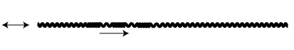
When the cord is stretched out, you can flick one end of the cord up and down, and send a wave along the cord as illustrated below:
![]()
This is a transverse wave; the wave is traveling to the right along the string, but the vibrations of the wave are moving perpendicularly to the direction of motion. We may also create a second, independent, transverse wave by flicking the end of the cord from left to right:
![]()
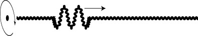
We may also create a completely different sort of wave by grabbing a handful of coils, pulling them, and releasing. Regions of higher and lower coil density travel along the cord:
This is a longitudinal wave; the vibrations of the wave move in the same direction that the wave is traveling.
A string or phone cord can support both longitudinal and transverse waves. Sound waves are longitudinal waves; the wave consists of regions of higher and lower air density compressing in the direction of motion. Light traveling in free space, away from any material boundaries, is a transverse wave: the electric field E and the magnetic field H of the wave oscillate transversely to the direction of motion and perpendicular to each other. An example of this is shown below:

The ‘active ingredient’ in light is the electric field. As discovered experimentally by Otto Wiener in 1890, the electric field is the component of light which is involved in chemical and material interactions. When we refer to the state of polarization of the light field, we are referring to the behavior of the electric field.
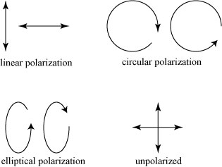
What sort of behavior are we referring to? Returning to the phone cord ‘model’, when we create waves on the cord by moving it straight up and down or straight left and right, we are creating a state of linear polarization: if we look at the cord head on, we find that the oscillations of the cord trace out a line. We can also excite the cord in a slightly different way: by moving our arm in a circular path, as if we’re turning a crank:
This is known as circular polarization, and it is distinct from linear polarization. Just like there are two independent types of linear polarization (horizontal and vertical), there are two independent types of circular polarization (clockwise and counter-clockwise). We may also move our arm in an elliptical path, and produce elliptical polarization. There is one final, very important, possibility: we can arbitrarily alternate between flicking the cord up and down versus left and right: such a wave is referred to as unpolarized. If we look at the cord head-on, the various possibilities appear as follows:
Polarization is not something we can easily observe with the naked eye (though some people are sensitive to it, a phenomena known as Haidinger’s brush). Natural light, produced by the Sun or an ordinary lightbulb, is unpolarized. In interactions with matter, however, light can become polarized, and there are a number of interesting effects and applications which can arise.
The discovery of polarization helped to convince early optics researchers of the wave nature of light. In 1669 the Danish mathematician Erasmus Bartholinus observed that light passing through a piece of Iceland spar (calcite) produced two images, in a phenomenon known as double refraction. An illustration of this (taken from Wikipedia) is shown below:
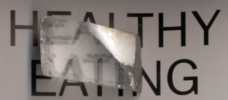
An exact understanding of this phenomena eluded researchers for quite some time. It fell to the versatile scientist Thomas Young to solve the problem; in 1803, he demonstrated that polarization phenomena result from the transverse nature of light. Along with this demonstration came a preliminary explanation of double refraction. Unpolarized light consists of a combination of two different polarization states (up/down, left/right). For a crystal such as calcite, the crystal structure results in one component of the polarization traveling faster than the other. Since refraction depends on the speed of a light wave, the result is that the two components of the polarization produce two different images.
One can convert an unpolarized light field to a linearly polarized light field by use of a polarizer. The simplest form of a polarizer consists of a fine grid of metal wires. For light which is polarized parallel to the wires, the light’s electric field induces electric currents in the wires which absorb and reflect the field. The other polarization, perpendicular to the wires, cannot excite such currents and passes freely through the polarizer. This is illustrated schematically below:
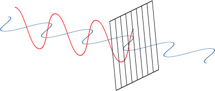
The vertically polarized field (red) is blocked by the vertical wires of the polarizer, while the horizontally polarized field (blue) is free to pass.
One common use of polarizers (though not wire ones) is in polarized sunglasses. The lenses of the sunglassses are made of a polarized material. The optimal orientation of the polarizers is such that they block horizontally-polarized light; the reason for this was discovered by Scottish scientist Sir David Brewster in the early 1800s.
In general, when a light field is incident upon the surface of a medium, part of the light field is reflected from the surface and part of the field is transmitted into the surface. It turns out (for reasons too complicated to be covered in a ‘basics’ post) that the amount of light reflected at a surface depends on the polarization of the light. Light which is polarized parallel to the surface of the medium is generally reflected in greater amounts than light which is polarized perpendicular to the surface. At a certain special angle, now called Brewster’s angle, the light field polarized with a component perpendicular to the surface is totally transmitted into the medium. If an unpolarized light field is incident upon the surface at Brewster’s angle, the perpendicular component will be totally transmitted and the reflected light field will be completely horizontally polarized:
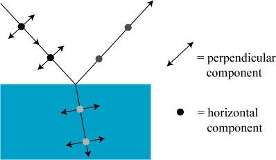
The practical consequence of this phenomenon is that when you observe light which has been reflected off a horizontal surface (a body of water, or the hood of a car) the light is mostly horizontally polarized. By designing polarizing sunglasses to block horizontally polarized light, one can block this unwanted glare.
A practical application of the Brewster angle is the production of a polarized light field from an unpolarized light field: the light reflected at the Brewster angle is completely horizontally polarized, and can then be used in experiments where polarized light is required.
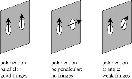
There is one other important observation to be made concerning horizontally and vertically polarized light: light of two different polarizations cannot produce interference. This discovery was made by Augustin Jean Fresnel and François Arago in a joint paper in 1819. One can imagine observing this effect by use of a Young’s double-slit interferometer (discussed in a previous post here). If the light illuminating the pair of slits has the same polarization, one will observe the expected interference fringes. If the light illuminating the pair of slits has perpendicular polarization, however, one will observe no interference fringes. If the relative polarization of the slits lies somewhere between these two cases, one will see faded interference fringes:
There is a lot more that can be said about polarization, but at this point any further discussion will go beyond the basics! I’ll try and return to other theoretical, and practical, considerations of polarization in future posts.


Very nice post.
One quick addition– you write:
It turns out (for reasons too complicated to be covered in a ‘basics’ post) that the amount of light reflected at a surface depends on the polarization of the light. Light which is polarized parallel to the surface of the medium is generally reflected in greater amounts than light which is polarized perpendicular to the surface. At a certain special angle, now called Brewster’s angle, the light field polarized with a component perpendicular to the surface is totally transmitted into the medium.
I’ve got a post from last year explaining Brewster’s angle in terms of moving charges. It’s got some hand-waving, but I think the general picture works pretty well to get the idea across.
The shorthand for Brewster’s angle I remember is “dipoles don’t radiate along their axis.” It helps me remember which polarization comes out of which face on a polarizing beamsplitter cube.
Chad & Tom: Thanks for the comments! Both fill in the gaps I left in discussing Brewster’s angle (I was starting to suffer from “This-post-needs-to-get-finished-itis” at that stage).
Pingback: Top Posts « WordPress.com
Nice article! Very clearly explained and ina very linear(ly polarized?) manner!! 🙂
Shanker: Thanks!
Stumbled across this a while back, forgot I had this tab open, meant to comment on this with something I thought you might find intriguing.
Linear polarization and circular polarization are different bases for describing the same thing, not always separate types of polarization. How do we know this?
There’s a nearly century old tradition of ionospheric plasma investigations. The fundamental tool for these is radio waves, i.e., a radar modified to transmit and receive in the proper band of frequencies. Toss one of these on a satellite and you have the Radio Plasma Imager, and instrument on NASA’s now-lost satellite, IMAGE. RPI had 3 crossed dipole antennae. The antenna along the rotational access only received, while the other two could transmit and receive. At least, that was the original plan. One of the transmitters burned out almost immediately upon orbit. There was an elaborate mathematical workaround for getting the polarization and directional information that was originally supposed to be easily derivable from signals from the crossed dipole transmitters, but this turned out to be unnecessary.
Ions are heavier than electrons and thus are affected less strongly by an electric field; both flavors of charge are constrained by magnetic field lines as well. These circumstances conspire to make magnetized plasma a refractive medium for electromagnetic waves that links linear and elliptical polarization (keeping in mind that circular polarization is a special case of elliptical polarization).
It was quickly discovered that whenever a radio wave ended up propagating quasi-parallel to a magnetic field line (say, within 15 degrees), the refractive properties of the magnetized plasma caused the linearly polarized signal to separate into two circularly polarized modes. One is the left-hand ordinary polarized mode, whose reflection is determined by local electron number density, while the other is a right-hand extraordinary polarized mode whose reflection is also affected local magnetic field strength. In essence, Faraday rotation but at much lower frequencies than normally observed in stellar signals. How did they determine that this was actually happening? The reflections were much stronger for waves traveling along the field lines than for those traveling obliquely through the magnetosphere before reflecting: guided waves.
BTW, left-hand is the direction an ion gyrates around a magnetic field. Right-hand is similarly the direction for an electron.
So, is it correct to conclude that since Young used light reflected from a “looking glass” (mirror) for his original experiment, the light was thus polarized, and had he used direct sunlight, he would not have seen the interference?
Ben: That would be correct! Unpolarized light would produce no visible interference effects.
“One can convert an unpolarized light field to a linearly polarized light field by use of a polarizer. The simplest form of a polarizer consists of a fine grid of metal wires. For light which is polarized parallel to the wires, the light’s electric field induces electric currents in the wires which absorb and reflect the field. The other polarization, perpendicular to the wires, cannot excite such currents and passes freely through the polarizer.”
For simplicity, say it’s coherent light. Which direction is the electric current? Or is it alternating current at the frequency of the light?
Could it be the magnetic component of the light that induces the electric currents? The wires presumably do cut the magnetic lines of force.
Or is some other viewpoint more useful?
Pingback: Optics basics: surface plasmons | Skulls in the Stars
Pingback: Faraday brings light and magnetism together (1845) | Skulls in the Stars