
I’m prepping a new course to teach this semester: undergraduate Electromagnetism II! I’m trying to put together some nice simple demos to illustrate principles in the class, and I’ll blog some of those that work and are interesting.
When Michael Faraday discovered the phenomenon of electromagnetic induction in 1831, paving the way for the complete unification of electricity and magnetism, he came up with a variety of experiments to demonstrate the effect.
One of them is now known as the Faraday disk, and it is very easy to construct — though I ended up buying one. My version is shown below.
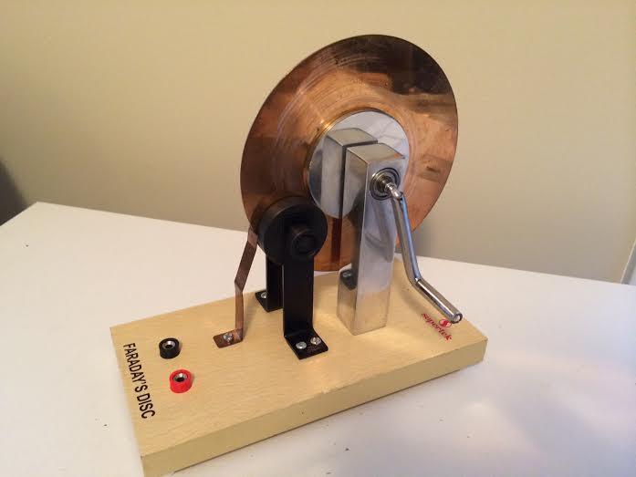
All of the parts are visible in this photo. By turning a hand crank, one rotates a copper disk between a pair of magnets (the black disks), one generates an electrical current that runs from the outer edge of the disk to the central axis. Wires connected to these two points runs to the red and black plugs, through which one can measure the voltage difference generated. It isn’t a spectacular amount — I measured about 5 millivolts, max — but it demonstrates the phenomenon known as rotational electromotive force.
As we have noted, however, Faraday interpreted his disk experiment as electromagnetic induction, not rotational emf. It turns out that he was kinda wrong — but he was also kinda right! The explanation of this simple experiment involves some rather deep concepts in physics, and inevitably leads us to Einstein’s theory of special relativity.
To understand the operation of the Faraday disk, we first need to understand the fundamentals of magnetism on a microscopic level. It will initially look very different from the “bar magnet and compass” intuition that most of us grew up with, but we will make the connection once we have some information.
Let’s start, however, even simpler: with electricity. Most people are roughly familiar with the behavior of forces between electric charges: opposite charges attract, like charges repel, and the force acts along the line between the charges. We typically break this process into two parts: one charge emits an electric field*, and the other charge is attracted or repelled by the electric field, depending on its sign.

Magnetism can also be consider a force between charges; however, the force only appears when charges are moving. We will not worry ourselves with how magnetic fields are created — that involves a painful amount of explanation — and will only worry about how a moving charge interacts with an existing magnetic field.
It is an experimental fact that a positive electric charge moving in a magnetic field experiences a force that is perpendicular to both the direction of the magnetic field and the direction that the particle is moving. However, that leaves two possible directions; the correct one is specified by the “right-hand rule”: point your right index finger along the velocity of the particle and your right middle finger along the direction of the field. The magnetic force on the particle then roughly points along the direction of the thumb.

A lovely hand model illustrates the right-hand rule for magnetic force.
A little more detail here will help in a moment: the force is strongest when the magnetic field and velocity are completely perpendicular to each other, and the force is zero when the velocity is completely parallel to the magnetic field.
As already noted, this picture seems strikingly different from the behavior of ordinary magnets! Magnets have a North and South pole: like poles repel, and opposite poles attract. There are not any obvious moving charges in these magnets, either.
On an atomic level, however, we can imagine that electrons orbiting atomic nuclei act as little loops of electrical current. In a magnetized piece of iron, these little current loops are all aligned, making the magnet, in effect, one big current loop.

The black loops represent an electrical current going in a circle; the red lines, which are pointing out of the loop, represent the direction of “magnetization” of the atoms and, consequently, the whole magnet.
So what happens when one of these current loops is exposed to a magnet field? A current is simply collection of moving charges; our current loop will, in general, experience a force from a magnetic field.
Let’s look at a special case of this and imagine a current loop that is perfectly aligned with a magnetic field. For clarity, I’m going to draw our loop as square instead of round; the results described will not change.

So what happens? Using the right-hand rule, we find that the forces on each “leg” of current in our square loop all pull within the plane of the loop itself. Furthermore, because of the symmetry of the problem, the force on the right leg of the loop is equal and opposite to that of the left leg — they cancel completely! Similarly, the forces on the front and back legs of the loop also cancel. The only action of the forces is to try and stretch the loop — the loop does not move or rotate.
What happens when a loop is not aligned with the field? We could do lots of math to determine the result, but let me just state the conclusion, which is plausible in light of our previous discussion: the forces on the loop tend to rotate it until it reaches a point where it is stable. In other words, the loop experiences a torque that aligns it with the magnetic field.
To make the final connection between our statement that “magnetic forces act on moving charges” and the bar magnets we know and love, we note that the magnetic field produced by a loop of current — and therefore also by a bar magnet — looks something like the picture illustrated below.

The magnetic field lines pass through the loop of current and then take a wide path around the outside of the loop to eventually come back through the bottom again.
What happens when we put two bar magnets together? The magnets will attempt to orient themselves so that their magnetization (red lines) align with the magnetic field lines of the other. The two ways this can happen are illustrated below: either the magnets line up such that their North and South poles are touching, or they align side-by-side with North and South next to each other. To phrase it in terms of our pictures, the magnets want to line up such that the red lines are parallel to the blue lines.

All of this description is somewhat beside the point, as it really just demonstrates that our statement that “magnetic fields act on moving charges” is consistent with our everyday picture of magnetism. Now we can apply our new impression of magnetism to understand how the Faraday disk operates.
Let’s consider a simple system that consists of a wire loop that is being pulled through a magnetic field, as shown below. The magnetic field extends throughout the blue region and points into the page; the wire loop is being pulled to the right at a constant velocity.

The circles with crosses are the magnetic field lines, pointing into the screen (the “X” is the tail feathers of the arrow). At first, it would seem that nothing much should happen when we pull the loop. However, an electrically neutral wire consists of positive ions and loosely-bound electrons; when the wire is moved to the right, those electrons are moved as well. The electrons therefore have a right-going velocity and, using the right-hand rule, it suggests that the negatively-charged electrons move downward. This is the same as a (positive) current traveling upwards! In the two horizontal legs of the wire, the electrons are pressed upwards but, since they have nowhere to go, the magnetic force has no effect.
The electrons moving upward in the left side of the loop, however, push other electrons ahead of them, resulting in a complete current flow around the entire circumference! This pushing of electrons by the magnetic field is referred to as an electromotive force, or emf for short. There are many ways to push electrons around a loop, though, and the force produced by a moving loop in a magnetic field is referred to as a motional electromotive force.
With this simple example, we can now explain the Faraday disk. We envision the solid disk as a collection of wires emanating radially from the central axis, as we illustrate in the picture below.

Now I’ve drawn the picture with the magnetic field pointing out of the screen; thus you see the “tip” of the field “arrow.” Using the right-hand rule, we can see that the wire currently passing through the magnetic field will experience a magnetic force that pushes a current from the axis to the outer rim of the wheel. If we replace our wire disk with a solid metal disk, the basic idea remains the same, although the current is free to spread out over a larger area of the disk as it travels from the center to the rim. This is, in fact a major source of inefficiency of the Faraday disk: current can “spill out” around the region where the magnetic field is present and flow back towards the axis. It’s kind of analogous to trying to push a volume of water uphill with your hands: sure, you might get some water to go up, but you’ll lose a lot spilling out on either side.
The Faraday disk is, in fact, the earliest example of an electrical generator, and is known as a homopolar generator. Like all generators, it converts mechanical work — in this case the effort to crank the wheel — into electrical energy through the use of magnetism.
I noted that the Faraday disk tends to be inefficient, but on a large scale they work really well as a way to store a large amount of mechanical energy and dump it very quickly, on demand, into electricity. Basically, if you make a large, heavy, spinning metal disk, switching on a strong magnetic field will make that disk dump its energy of rotation into a massive pulse of current. Such a device was built in the 1950s by Sir Mark Oliphant at Australian National University where it was used in synchrotron experiments until 1962. The remains of it still remain, as pictured below.

Remains of the homopolar generator at ANU, via Wikipedia.
Practical uses aside, there is still more we can learn from homopolar generators and their relatives. Returning to our simple model earlier, involving a wire loop being pulled through a magnetic field, let’s imagine that a visitor happens across our experiment and walks by it at the same speed and in the same direction that the wire is moving. From his perspective, then, he sees a different experiment.

This may not seem like a significant change, but it turns out to be a very big deal, indeed! Because the loop is not moving from the visitor’s perspective, there are no moving charges and therefore the magnetic field does not affect the electrons in the loop at all! It seems, from our simple argument, that the visitor would not see a current flow, while the experimenter would see a current flow.
This obviously cannot be the case; an electron moving from the bottom of the wire loop to the top of the wire loop is a definite event that everyone should agree either happened or did not happen. This leaves us two possibilities to reconcile what appears to be a paradox: (1) The laws of physics, as we know them, are only valid for one of the observers, namely the experimenter. He, and anyone who is standing still like him, represent the true arbiters of physical law. (2) There is some additional physical law that we have not addressed yet that makes the two observers agree on the experimental result.
At the beginning of the 19th century, most scientists would have argued in favor of option (1). As I have discussed many times on this blog**, throughout most of the 19th century it was believed that light waves propagate via the motion of a mysterious, intangible substance permeating all of space, the “aether.” Just as water waves travel in water and sound waves travel in air, it was reasoned that light waves must travel in this aetherial substance. Motion of the Earth with respect to the aether was in principle measurable, and it was assumed that the laws of physics would only have a universal form for a person at rest with the aether. Though the relationship between light, electricity and magnetism would not be discovered until James Clerk Maxwell’s work of 1865, most scientists would not be terribly bothered in assuming that electricity and magnetism also have a preferred frame of operation.
We know now, however, thanks to Einstein’s theory of special relativity, that the laws of physics are in general independent of the constant motion of those observing them. This means that the observer walking past our loop experiment must also see a current generated in the loop; but where does this current come from?
The answer was provided by Michael Faraday in 1831, when he discovered the phenomenon of electromagnetic induction. In short, Faraday discovered that a time-varying magnetic field induces a circulating electric field, as illustrated below.

A magnetic field that is constant in time does not produce any electric field. If we change the magnetic field flowing through a region, either by changing the power of the magnet or by moving the magnet, we create a circulating magnetic field.
Let’s look at the experiment from the point of view of our walking visitor again. From his perspective, he sees the total effect of the magnetic field in the loop (what we call the flux) decreasing as the magnet moves away to the left. By Faraday’s law, we know that this changing magnetic field creates an electric field that circulates around the loop in a clockwise sense. This electric field drives the current around the loop***, and both the experimenter and visitor agree that a current is moving; they would just disagree on the origin of that current.

Curiously, Faraday discovered both electromagnetic induction and motional emf at the same time; both were discussed in his 1831 paper**** and he introduced what we now call the Faraday disk in that paper.

Faraday treated motional emf and induction as being two aspects of the same phenomenon, though we have seen that they are evidently produced by different forces: motional emf comes from the magnetic field, while induction comes from an induced electric field. So Faraday was somewhat wrong in his analysis, but he was also accidentally right: in Einstein’s special theory of relativity, electric and magnetic fields are two aspects of the same electromagnetic phenomenon. The magnetic field seen by our stationary experimenter is perceived by the walking visitor as an electric field. Einstein’s first paper on special relativity in fact discussed in detail how magnetic and electric fields transform into one another when one changes to a different moving frame of reference. So, in fact, Faraday was also right in thinking of motional emf and induction as the same thing!
Looking back, our discussion has taken us from a really crappy electrical generator into the relativistic unification of electricity and magnetism. The Faraday disk is a nice example that shows us that even the simplest of physics demonstrations can often take us into quite deep and profound aspects of nature.
******************
* For a discussion of how to interpret diagrams of fields, see my old “optics basics” post.
** See, for instance, here and here.
*** I’ve taken some liberties in showing the electric field running all the way around the loop. In reality, the electric field would only appear in those regions where the magnetic field is changing: namely, right at the boundary of where the field cuts off. My simple picture does not allow us to draw the fields in a sensible way here, however.
**** Philosophical Transactions of the Royal Society of London, vol. 122 (1832), 125-162.


“that leaves two possible directions; the correct one is specified by the “right-hand rule””
I understand this question is probably either a massive can of worms or a rather stupid question (possibly both), but why is the right-hand rule the correct one? Why isn’t the “left-hand rule” a thing here?
I understand that this is the sort of thing that can be verified experimentally, but I’m not sure what the reason behind this rule is. My intuition (which is obviously wrong here) tells me that physical laws should be symmetrical, so it feels irksome to see it picking what seems like an arbitrary direction. Do we have any idea why this is the direction the force is applied in, and not the opposite direction?
Hadn’t really thought about it in detail before, but I think the answer is: there *is* a left-hand rule for *negatively* charged particles! The “right-hand rule” is based on the assumption that the charge in question is positive. If, historically, we had labeled the + and – charges opposite to what Benjamin Franklin did, we would be talking about the “left-hand rule.”
That certainly feels much more satisfying to my intuition 😛
I recently watched a bunch of videos on gyroscopic precession on YouTube (which blew my mind; I got a toy gyroscope to play around with it, amazing stuff) and had the same initial reaction that the apparent asymmetry seemed jarring to my intuition.
In that case, I actually found this video most informing as it seemed to explain why precession happened in that particular direction: https://www.youtube.com/watch?v=TUgwaKebHTs
Physical laws can be mirror-asymmetric (beta-decay) . 3-D coordinates are chiral (paired shoes). Resolved chiral probes (left foot) lift chiral degeneracy (shoes fit with different energies). Handed rules for angular momenta; pseudovectors, pseudotensors.
Massless boson photons detect no vacuum refraction, dispersion, dissipation, dichroism, gyrotropy. Postulate this is exactly true for fermionic matter (quarks). Parity violations, symmetry breakings, chiral anomalies, baryogenesis, Chern-Simons repair of Einstein-Hilbert action suggest vacuum trace chiral anisotropy acting only upon hadrons. Noether’s theorems couple exact vacuum isotropy to angular momentum conservation. If fermionic matter leaks Milgrom acceleration, dark matter disappears .
Test spacetime geometry geometrically, not with composition or field. Six classes of chemical tests could reshape physics. Cartography showed Euclid was incomplete. Look for a black swan.
Fleming’s right-hand rule applies to generators (as here). The left-hand rule applies to motors, or any situation that has movement as an output; electric bell, loudspeaker etc. I note that the name “Fleming” does not appear in this discussion. Is this only used in UK?
I want to know as well about the velocity(speed) of motion at the armature how it could effect up or down with changing of EMF and the induction and also i need to know how we can have a constant velocity in the different types of motor as if we connect the windings in parallel,series or compound connection.
Also when the movement is parallel or anti-parallel with the magnetic field does the movement will affect with this change or the movement always leading the affect by put it on or take it of on the magnetic field and magnetic field is follow the movement affect with a reaction by inducing EMF or not.
Can you please give more detailed instructions on building a homopolar generator? And can you please tell me where you bought your faraday disk? Thank you!
A simple version of a homopolar motor is described in this post of mine: https://skullsinthestars.com/2014/12/12/the-mystery-of-the-magnetic-train/
Also, my Faraday disc I got from Sargent Welch: https://sargentwelch.com/store/catalog/product.jsp?catalog_number=WLS1815-43
Hi LAN
Thanks for asking and as there is too many interests with my idea so i try to put every thing together by myself and i faced many hard difficulties because i,m not an engineer and i can describe myself a thinker or ideas maker so for this purpose i starts studying by myself and i need more knowlage and i,m seeking for a scholarship as an independent researcher and the best think i can do is i can share my work after finish it with scholarship fund raise either a person or organisation .
By the way the principle is correct by i came into the designing field and i already changed the design of one part and it need more refining and i need to do further study on the result.
Finally i will be very appreciate if i receive an offer for scholarship .
Best regards
Yours
Esam
Can you make this page downloadable?
Yes the page is dowmnloadable
Hi Ian
Electrically and mathematically for example if we have a motor running by DC on 24 V. DC resource and using 22 AMP DC.. And Reducing in minimum a 40 AMP DC with 0.5 AMP AC
How much you think you can improve this Motor?
What level of producing Energy you can reach?
Hopefully i can get an explanation from you
Thank you in advance
The “Faraday Paradox” remains… why does this generator still work if there is no relative motion between the magnet and the copper disc? The two can, in fact, be glued together, and there will still be power generated between the ID and OD of the rotating disc/magnet… just as described above. I’m honestly seeking a proper explanation of this… it’s not a ruse.
It also works of the magnet/disc are completely stationary, and just the contact point rotates.
I forgot to state that in my above question, the magnet and copper disc are the same size/shape… the magnetic field is uniform across the entirety of the copper disc.
The answer is thought to be that the magnetic field does not change, or move, when the magnet is rotated in line with the field. So the disk is still moving through the magnetic field. It also works if there is no disk, and only the magnet rotates.
I’ve heard that explanation before… and my thoughts as to “why” are that maybe the flux gets tied into alignment with other predominant fields around… like the earth.
The final question is… if the magnet/disc (or nickel plated magnet) are stationary, and the contacts rotate relative to the magnet/disc, it still works… why? Is it just because the periphery contact wire is moving through the field? I’ve seen that it still generates voltage, but I’ve not seen enough testing to prove that it still generates the massive current as the “normal” mode of operation.
ronchinnery … I’d like to talk to you. You obviously know the details. I’ve had a long interest in Tesla’s Unipolar Dynamo. … I just reviewed a Paper I downloaded at some time, by A. G. Kelly, PhD CEng FASME FIMechE. He states that the magnetic field is not fixed, like everyone thinks. His test results show that the field lines move with the magnet. He claims the voltage is in relation to the external measuring circuit. It’s a PDF. I’ll need to find the link to it for you, or search “Faraday’s Final Riddle; Does the Field Rotate with a Magnet”.
I assume that the voltage, from two contacts only, is a weak one from the brushes only. I hadn’t heard of that before. … Bob
Here’s a link. http://distinti.com/docs/papersFromOthers/KellyFa3.pdf
Then again, he may be wrong. Just saw a magnet rotating under a dish of ferrofluid. It stays the same.
I just found a video by another scientist that shows Kelly is wrong.
Rotating the magnet fixed with the disk proves that the field does not rotate with the magnet.
I thought I understood these devices, but this write-up has confused me to no end.
1. Regarding the magnet / electron current loops illustration… the first paragraph describes electrons as loops of current in this magnet. The second paragraph suggests subjecting these “loops” to a magnetic field. What idea is this trying to convey? They are already subjected to a magnetic field, as described in p1. Furthermore, considering electron orbital theory, isn’t it misleading to describe them as current loops?
2. The right hand rule, which is described as the index finger pointing forward representing Velocity, the thumb upwards representing a Force, and the middle finger curved inwards representing the magnetic field. Later, “ Now I’ve drawn the picture with the magnetic field pointing out of the screen … Using the right-hand rule, we can see that the wire currently passing through the magnetic field will experience a magnetic force that pushes a current from the axis to the outer rim of the wheel.”
This sentence needs to decide if it’s talking about the direction of the current, previously defined as V, pointer finger, or the force, previously undefined but described as perpendicular to V. Therefore, up/thumb. The image associated with it also swaps the velocity of the “wire” to the thumb/pressure direction and the velocity (described now as the FORCE) to the velocity vector.
3. In a field pointing into the page, “ an electrically neutral wire consists of positive ions and loosely-bound electrons; when the wire is moved to the right, those electrons are moved as well. The electrons therefore have a right-going velocity and, using the rright-hand rule, it suggests that the negatively echarged electrons move downward“
So they have a right going velocity because we are moving them to the right, but also by the hand rule, the “negatively charged” electrons move downwards? Why downwards, when the right hand rule very clearly gives an upwards force because of the “inwards” field, and the “pulling a coil example” rule very clearly says they are moving to the right?
I went from a “fairly comfortable” to “frustrated and confused” after reading this, and it hasn’t even talked about faraday disks yet.
Click on right and print to pdf printing. Or click on page and save to …
What the author of this article does not say is why no current is produced when we rotating the magnet alone under the disk, and why current is produced when we simultaneously we rotating the magnet and the disk at the same speed and in the same direction, i.e. we do not move them in the opposite direction. But the curent is induced.
I am wondering if, this many years after 2014, the author is interested in a possible Faraday Disc application from about the 1880s. I have an early polyphon disc music player different than other photos I have found online. It uses a crank wheel & belt that drives 4 glass discs (14-15″ diameter) w tape that I think keeps copper or aluminum small (1″) discs in place. Copper? wire ends are used in about 4 places, collecting electrical energy? Difficult to describe. I have taken it apart, cleaning & repairing, but still trying to figure out where some loose parts go. Let me know if you want photos & can help me make this thing work again to play large metal music discs.