
This past week, thanks to Laughing Squid and other sources, a lot of people watched and were amazed by this simple demonstration of electromagnetism in action.
It is billed as the “world’s simplest electric train,” and it is almost certainly the case. Using only a battery, some strong magnets and some (bare) coiled copper wire, one can make the “train” travel numerous circuits through the copper “track,” until the battery is completely drained.
This caught my attention because it is a very clever twist on one of Michael Faraday’s original discoveries! Not electromagnetic induction, as I reflexively thought, but a homopolar motor. Below is an animation of such a motor that I whipped up in my office.

A simple homopolar motor. Just in case you don’t believe it actually works, a longer video is here.
This particular homopolar motor design is ridiculously simple: a pair of neodymium magnets are stuck (by magnetic force only) to the bottom of an AA battery. A wire loop is balanced on the top of the battery, bent so that it touches the magnets on the bottom. When the connection is made, the wire will start to spin immediately, and will in general start spinning so fast that it will flip itself off of its perch. More sophisticated and stable designs exist, but this one is quick and showy.
So how does the homopolar motor work, and the “magneto-electric” train shown in the video? Both of them depend on the relationship between moving electric charges and magnetism, albeit in somewhat different ways.
Our story begins at the birth of what we now call “electromagnetism,” the beginning of a theory of nature that considers electricity and magnetism to be inextricably linked. It began in 1820, when the Danish physicist Hans Christian Oersted demonstrated that a magnetic compass needle can be deflected by an electric current, proving that moving electrical charges produce a magnetic field. Before this stunning experiment, it was generally assumed that electricity and magnetism were two completely separate physical phenomena.
What Oersted discovered, in essence, is that electricity flowing through a long straight wire creates a circulating magnetic field around it, as illustrated below.

A few of the magnetic field lines around an electrical current, I, in a really long wire.
For those unfamiliar with this graphical depiction of “fields,” I have written a “basics” post on the subject. One should picture these fields circulating around the wire at all heights and distances, being denser closer to the wire. Without going into too much detail how we know this, we note that the B-field represents a field of force that interacts with any permanent magnet brought nearby. Such a permanent magnet will tend to do two things in a magnetic field: it will rotate to line up its North Pole with the field lines, and it will be drawn into a region with a stronger field, i.e. denser collection of field lines.
The field lines circulate around an electrical current in a sense that can be determined by the “right-hand rule”: pointing the thumb of your right hand in the direction of the current, the field lines will circulate in a sense determined by your fingers.
We can use this right-hand rule to also describe the fields around a loop of circulating current; in such a case, the field lines appear roughly as shown below.
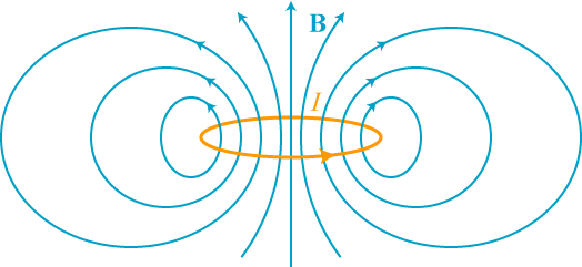
The field of a magnetic dipole.
Once we’ve made a closed loop, the field lines are fundamentally different from the straight wire. The field lines of the long wire have a handedness — that is, they circulate around in a right-handed sense — but they do not have a “side” to them. The loop, however, has what we might call a “top” and a “bottom” or, more appropriately, a “North” and “South” pole. The North side of the loop is the side from which the field lines emanate, while the South side is the side into which the field lines pass. This loop has two poles, and is therefore referred to as a dipole.
This language of poles is suggestive of a regular bar magnet and the magnetic Earth, and that is of course the point — to a good approximation, a loop of current, the Earth, and a simple bar magnet all have a similar dipole field structure. For instance, here’s a sketch of the magnetic field of the Earth, with corresponding bar magnet superimposed.
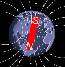
The Earth as a gigantic bar magnet. Note that magnetic North (the magnet’s South pole) is angled from the true North pole. (source)
The takeaway lesson here is that a loop of current will behave pretty much the same as an ordinary permanent magnet; that is, North and South poles will attract, while North-North and South-South combinations will repel.
This immediately gives us a simple explanation of how the “magneto-electric train” works! When we place our battery, capped with magnets, inside the coil, we complete a circuit and a current flows through the coil. The coil is, in essence, multiple loops of current stacked on top of one another, and the result is that the region of coil between the permanent magnets is a magnet itself!
We illustrate the situation below. What happens: the “virtual bar magnet” created by the current flowing through the coil pushes the magnet in front and pulls the magnet behind. Of course the battery between them gets taken along for the ride!
 This highlights an important point that wasn’t covered in the original video above — at least according to my experiments, it is necessary to make sure that the two magnets on either end of the battery have their North poles pointing in opposite directions! Otherwise, they are either both pushing or both pulling, and the “train” doesn’t move.
Here’s my own short demonstration of the “magneto-electric train.” It is surprisingly easy and cheap to put together. I used a AAA battery as the power source, and a pair of strong neodymium magnets I had on hand; to give the train more “oomph,” additional magnets could be used on either side of the battery. I used 18 gauge copper wire for the coil, and wrapped it around a 1/2” ring stand to coil it. It is important that the wire be uncoated — otherwise current will not flow and nothing will happen! The 18 gauge wire seemed like the right balance of being easy to bend but rigid enough to hold a shape. Also, it was all I could find at short notice.
With this explained, we can now turn back to the homopolar motor, which uses similar physics to make it spin. Again, we have an electric current producing a magnetic field that interacts with a permanent magnet, but the interaction is a little more complicated.
A little extra history is worth sharing here. We have already noted that the first link between electricity and magnetism was discovered by Oersted in 1820. A number of scientists immediately saw the possibility of building an electric motor, including Michael Faraday‘s supervisor Humphry Davy, but their attempts to make one failed. In 1821, however, Michael Faraday began his first real scientific job as Assistant Superintendent of the House of the Royal Institution. Inspired by Davy’s work, he began his own investigations and quickly invented the homopolar motor; the illustration of his original device is shown below.*
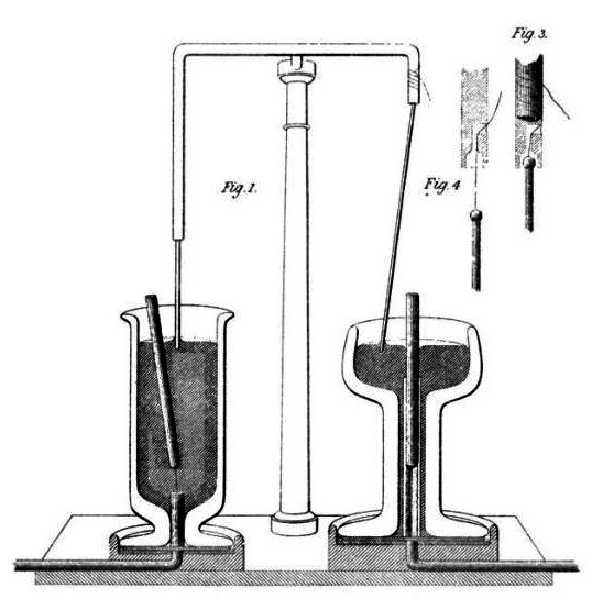
Illustration of Faraday’s magnetic rotation device, via Wikipedia.
There are two devices pictured here. The one on the right is closest to mine: a hanging wire dips into a container of electrically-conducting mercury, with an electrical ground coming through the bottom and a permanent magnet in the center of the container. When a current is run through the wire and the mercury, the wire circles around the magnet. In the system on the left, the wire is fixed in the center of the container, and the magnet ends up circling around the wire when the current is applied.
There is one significant difference between the magneto-electric train and the homopolar motor. Where the train uses the magnetic field of a current to push magnets, the motor uses the field of a magnet to push the electrical current.
To explain the the motor, we therefore need one more piece of information: how a magnetic field effects moving charges. An electric current produces a magnetic field, but the moving charges of an electric current also experience a force due to a magnetic field. If we look at a single charge, we know from experiment that the force on it due to magnetism satisfies a different sort of “right-hand rule,” as shown below.
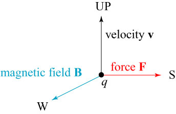
For this right-hand rule, we point our index finger in the direction the charge is moving, our middle finger in the direction that the magnetic field is pointing, and our thumb points in the direction of the force the charge experiences. Therefore, an upward-moving positively-charged particle moving in a magnetic field pointing West will experience a force to the South. One consequence of this is that a charge particle moving parallel to a magnetic field will experience no magnetic force at all.
I was asked an interesting question about this recently: why does a charged particle experience a “right-hand rule” force? Why not a left-hand rule? The answer is that a negatively-charged particle does move in the opposite direction, following the left-hand rule! Since the definition of what we call a positive charge and what we call a negative charge was somewhat arbitrarily chosen by Benjamin Franklin in the mid-1700s, we might very well have spoken of a left-hand rule if he had chosen differently!
Now let’s see how this applies to the homopolar motor, as illustrated below. The current (and therefore the electric charge) flows from the top of the battery through both arms of the wire loop and down through the magnet at the bottom. Using our new right-hand rule on the right side of the wire, we see that the force on the moving charges, and therefore the wire, points out of the screen; we mark several of these points with red dots. Using the right-hand rule on the left side of the wire, we see that the force on the moving charges, and therefore the wire, points into the screen; we mark these points with blue dots. (Don’t be afraid to actually hold your hand up to visualize things — this is exactly what physicists-in-training, and physicists like me, do.)

The net result: the right side of the loop gets pulled, the left side gets pushed. The wire loop spins around its balance point on the battery, and we have a motor!
Both the homopolar motor and the magneto-electric train are really eye-catching demonstrations. They use same physics that makes all electric generators and electric motors work, but somehow their simplicity really drives home the fact that this is fundamental physics at play, and not some clever engineering trick. I encourage everyone to give them a try — it is remarkably inexpensive to play with some of the greatest scientific discoveries in history!
***************************
* Michael Faraday, “Description of an electro-magnetical apparatus for the exhibition of rotary motion,” Quarterly Journal of Science 12 (1821), 283.


Any thoughts of how to recharge the battery by its motion through other equipment?
Thoughts of free electric device. Yes I know the Government will never allow a patent on anything to do with free power. Past history proves this.
If it is really great they send the goon squad and steal it, then have you arrested and released after they have trained you never do that again.
Dear Bob, This is not a free energy device at all. It is using energy from battery- chemical energy- electrical energy- kinetic energy . Free Energy device is a myth. Believe me- that thing is not possible. You can not cross the boundary set by “Law of Conservation of Energy” until and unless you are able to convert mass into energy.
Your assertions are refuted by Howard Johnson’s motor and Reidar Finsrud’s mobile.
There is no free power. Go to school. Study algebra, calculus, then physics (w/calculus, not for poets). Convert yourself from a tin foil wrapped around head idiot to a trained scientist. Then you may post. But not till then.
Having difficulty getting this to work. Any advice? I have the same wire you have, AAA battery, and Neodymium magnets. I was able to get it to work somewhat a few times, but it always would get stuck. After about 3 hours playing with it, now I can’t get even a start of it working. Was hoping to use this for mystery reader for my son’s school.
The only immediate thought is to make sure your magnets on either end of the battery are pointing in opposite directions — which you can do by holding them carefully, confirming that they are repelling, and then attaching them to the battery in the same orientation. Also, if one orientation doesn’t work, try either flipping both sets of magnets over or just push the battery into the coil in the opposite direction.
Also, as you’ve probably noticed, the coil has to be wound pretty tight and (hopefully) with minimal defects/kinks in it, otherwise it readily gets hung up. I wound my wire painstakingly around a metal ringstand that I had on hand.
That was really helpful but still a stupid question in my mind. you know how the battery is labelled with one south and north end. so how come the top magnet gets fit as it suppose to get repel south to south end. “please reply need help”
P.S. More magnets equals more force! If you have extra magnets, you can try stacking 2 on each side to give the train a bit more “oomph!” I only used one on each side because it happened to be what I readily had on hand.
Sounds like your battery voltage might be low.
Great explanation of the effect. But your “virtual magnet” (created by the current in the solenoid) is pointing the wrong direction for the way you draw the current. Using the right hand rule, if your fingers wrap in the direction of current (CCW looking from above) then the magnetic moment will point upward. The picture just above of the “field of a magnetic dipole” is correct.
Reblogged this on PsychoMortem.
3 follow up experiements needed:
1. What would be the resulte if you dropped the loop and the magnetic motor in a free fall. I predict the result would be a torque. The loop would start rotating and the motor would still move through the loop. The forces in opposite directions would be equal.
2. What is the result if you were to fix the motor and the loop together? Would nothing happen because the force holding them together would cancel out the created force…I predict nothing would happen.
3. Do the 2nd experiement while doing the first. Would the static connection of the motor and loop still result in a torque on the sytem?
Hi
thank you so much for this in-depth explanation! I am slightly confused about two things though and would be very grateful for some help please
1. is the train an inverse homopolar motor or is it powered by the “bar magnet” that repels the front magnet and attracts the back magnet or is it a bit of both?
2. if it is a homopolar motor, what is the configuration of the current and magnetic field that results in a force which pushes the train through the copper wire tunnel? the wire spirals and when i use the right hand rule from different points of reference i end up with forces that point in towards the train rather than forward.
Trying this with the same materials above. Any explanation for why the copper wire is becoming unbearably hot? What might we be doing wrong?
Are you using thinner wire? Heat comes from joule heating, i.e. heating due to the electrical current. A too-thin wire might result in an overheated wire.
Thanks for responding. It’s 18 G copper wire. I noticed I am using a AA, as opposed to AAA battery (AAs are used in alternate versions of this train I have found). Would that cause the problem?
The battery might be the difference. Different battery sizes, and even types, can have different internal resistances. Smaller internal resistance means more current means hotter wire. Not sure of the relative resistances of AA versus AAA, but you could try the smaller battery and see if the heat is less. Does it work, otherwise?
Thanks for you help. We tried it with a AAA battery (new one), 0.3 in diameter neodymium magnets and 18 G bare copper wire. Good thing….no heat, but we got nothing else either. No movement, no pull. Tried using up to 3 magnets on each end of the battery. Also flipped the magnets on each end of the battery. Suggestions?
Not sure. Make sure that you flip the magnets on each end separately, and try flipping the whole magnet/battery arrangement around if it doesn’t work one way. If the coils aren’t wound tightly, the magnet could get hung up on the wire. Also, make sure there’s good contact between the magnets and the wire and, of course, the battery and the magnets.
Thank you for your detail explanation! But I hope I can see the right direction of the “Virtual magnet”. The link says I can’t find the page!
Skulls? Thank you this is really helping in my end of Diploma work for my Baccalaureate. I am doing it on how does voltage and magnetic strenghts affect the train, I was wodering if there were any equations that could be relevant to this topic.
The relevant equations would be Ampere’s law, relating currents to magnetic fields, and equations which describe forces on magnetic dipoles.
why the south pole of the magnet can face the south pole of the battery?shouldn’t it be south faces north?
The battery has no south pole!
Hello again. Finally was able to get our train to work. A couple of questions concerning the physics:
1. Using the right hand rule with the train set up I’m having a hard time understanding the direction of the magnetic field (index finger). If the thumb shows the direction the train is going (force) and the middle finger illustrates the current around the coils how is the magnetic field perpendicular to the actual magnets on the poles of the battery (if that makes sense)? What I am trying to do is photograph my son’s hand in the right configuration next to his train so he can show what’s going on visually -the index finger is tripping us up!
2. We have tested the time it takes for the battery to go through a 1 meter long copper coil with varying numbers of magnets (2, 4, 6 and 8). As suspected, the battery train with more magnets goes faster. Can you explain why more magnets results in greater speed scientifically? Appreciate your help!
Regarding number 2. As you add more magnets you increase the amount of attraction of the magnets to the magnetic field created by the coil and as there is more attraction the magnet can then move faster.
However it is important to keep in mind that as you increase the amount of magnets you also increase the mass of your “train”. Meaning that you are effectively slowing it down by weighing it down with another magnet, however the speed that the attractive strenght that the magnet adds is more than the action of weighing the ” train ” down.
If you didn’t understand I can try and explain again. I don’t have a fine way with words, but I hope this helps for number 2.
Regarding number 1. I am not sure but I don’t think the right hand rule can be applied to the coil.
If you want an explanation I have made one that i used for my work on this particular experiment. I will be posting here soon.
The forefinger is negative, the midfinger is north, and the thumb is foreward. This yields clockwise for a positive charge.
Can we use any other material like mild steel for making the coil ??
Pls reply soon, a bit urgent..
I doubt so as steel is a pretty poor conductor compared to copper you could try the experiment though and give us feedback on this comment.
Now use a watch battery and wind iron or holmium wire on the copper wire.
Why do we need only neodymium magnets and not any other kind?
This only works with neodymium because neodymium conducts electricity and that is what makes the “electro-” in electromagnet.
That, too!
what about passengers cabin? how it will stop at stations and start again for its next destination?
We can make small paper slips for stoping the train by breaking its electric flow. So place some paper strips for stoping @ the stations.
Hi. Does this work only with copper or with steel too?
I’d like to ask you few questions
about it to deepen my knowledge and who knows in the future do a school project.
– In the video we can see the rotation of the magnetic train on its own axis when it goes through the copper coil inner. Why is that happen? Is it a mechanics or electromagnetism effect?
– Is the induced current generated by the movement of the magnets (Faraday-Lenz’ law) intense enough to create a opposing force that slows up the magnetic train speed?
– What’s the most relevant parameter to improve the train speed?
If you could answer at least one of the questions above I’d be really happy!😁😁😁😁
The info given was very helpful. How much of coil(winded copper wire) is required to make 220 cm of track for electromagnetic train??please inform me as soon as possible.
Will it work equally well with ferrite magnet?
is it important to use bare copper wire ?
Bare copper wire is necessary because it conducts the current from the battery. Similarly, neodymium magnets are needed because they conduct electricity.
can we use other magnets instead of neodymium magnets ?
Free fall electrical recharge will always loose more than it would gain but the benefits of super low drag the energy producer mechanism pfps by multiple legacy equipment is interesting and very plausible
will the train move without neodymium magnets
I made it and it did not work. can anybody can help me?
As stated in the article, only North face of the magnets facing outwards at either end of the battery works. If South face points outwards at either end, it does not work. I did not quite understand why that’s the case? Please help me understand.
That was a lot of comments
Is there a way to pass current thru the wire by connecting its either ends to a power source and inside instead of a battery have a conducting tube having at its either ends – magnets?
ok
I followed the instructions carefully but the train is not showing any response . I took a new AAA battery , a bare copper wire and 6 neodymium magnet slightly smaller than the battery so can you tell me the problem and the solution too. As I have to show the project tomorrow 😭😭 😭
Your battery needs to be slightly smaller than the magnets!
Also make sure the magnets are facing the same way (NS——–SN)
Is this will work with cuboid shape magnet
The batteries must be WIDER in diameter than the battery. The magnets must be able to contact the wire to let electricity flow through the coil. re: short battery life– You are using the battery to power an electromagnet. This configuration effectively puts a dead short across the battery! re: optimum configuration– there is a pair of youtube videos (part 1 and part 2; don’t have the link handy) where the author tries a number of configurations of number of turns of the coil per inch (about 10 turns per inch, which balances performance vs being able to see the ‘train’ inside the coils), optimum number of magnets (four 1/8″ magnets at each end), optimum battery (he tested several brands of AAA batteries for optimum life– about 7 minutes was the best he could get). You could add more magnets, but you’re balancing optimum propulsion with weight of the entire ‘train–‘ too many batteries are too heavy for an AAA battery to push! Re: cuboid magnet– maybe– if it doesn’t get stuck in the coils! Maybe add a ‘nose’ to the magnet to guide it through the coils.
Guys, why between the magnets need to be a battery??? Why not to substitute the battery by wooden roller with a spike on both sides??? I really must know the answer, please help 😀
WHO INVENTED THIS ELECTROMAGNETIC COIL TRAIN!!!!
Hello? Anyone care to answer my question? Who invented the electromagnetic coil train?
HELLO SIR , PLEASE ANSWER…. IS THISS MODEL FOLLOWING LENZ’S LAW?
Yes.
Hi, I was wondering if I could use one of your diagrams, in a report. I would cite you as the source.
Feel free!
Thank you!
i was wondering after making this train does the length between each coil differentiate the speed
pls respond i am trying to find a 6th grade science fair idea using this train
yes. I am doing this for a science fair and they do.
pls respond as soon as possible
(:
i was wondering after making this train does the length between each coil differentiate the speed
pls respond i am trying to find a 6th grade science fair idea using this train
pls respond as soon as possible
(:
also can i use a diagram for my project i will cite you
The more windings you can stack between the magnets, the better. However, it is a limit where the windings is going to short circuit eachother when there is no spacing left between each winding.
You explained visually. ..
So impressive
i was wondering after making this train does the length between each coil differentiate the speed
pls respond i am trying to find a 6th grade science fair idea using this train
pls respond as soon as possible
(:
also can i use a diagram for my project i will cite you
it does, the coil has to be close but not too close to make it go the fastest
its crap. nothing is working
I did it and it worked for me. Make sure that the magnets are facing the same way on the battery (SN——-NS) And make sure you make the track tight. Also AAA work much better than AA.
If the electric loop in the homopolar motor is replaced with a permanentmagnet, what is the reason why that wont work (Yes, I’ve tried)?
Or is it ways to mimicking the electromagnet using a stack of vertically magnetized thin magnets, and between the spacing between them a stack of horizontally magnetized magnets. I mean, a way to merge these two magnetic fields into eachother without the magnets physically touching..
Thank you. Planning to use this as science project for my son. Will quote your website as the source for detailed explanation of the science behind the train. Hope it is ok. Thanks again.
You’re welcome!
Hey! Can I use your explanation in my project? It is really important. I will cite you as the source.
If you’re citing, that’s fine! Be sure to quote it or write it in your own words!
Please explaine more about Howard Johnson` s motor
I got the train working fine as a school project, it was really nice.
I have however one question that i want to anwser in my report, why does the train not work if the magnets are like this: ZN—–NZ ? I have tested it myself and I know for a fact that it doesn’t work, but why? I’m thinking it has to do with the magnetic fields maybe cancelling each other out but I’m not sure.
So does anyone know why?
Please double check the diagram of the “ virtual bar magnet”. According to our experiment, if the current is the same direction as your diagram and the attached magnet is same as yours, the car should move down instead up as your diagram. The polar of your “ virtual bar magnet” seems wrong.
hey i wrote a report on the electric train using your website as my source, please review it as soon as possible. ( keep in mind i’m very young )
There is an inextricable link between electric current and magnetism, this theory is known as “electromagnetism”, summarized, it means wherever an electric current is present, so will magnetism and vice versa. This theory is fundamental to understand how this experiment works. It takes particular use of magnetism being in the presence of an electric current. In this experiment we have used a battery, neodymium magnets and a (coiled) copper wire. The magnets have to be lined up in such a way that, if put together, would repel each other. The batteries provides an electric current to the magnets, from which the electrical current would flow to the copper wires, this would make a complete circuit and would (according to magnetism) create a magnetic field around the copper wire. When introduced to a electric current driven magnetic field, a permanent magnet would behave in one of two ways, it would either rotate to line up its north pole with the field lines (this behavior can be seen in Michael Faraday’s homopolar motor) or it would be drawn to an area of denser magnetic forces (which it does in this experiment). This electric current driven magnetic field would draw the our “train” forward as it becomes denser at different points, seeing the electric current would flow from one place to another, causing the “train” to move forward.
Hi there OP!
I’m presenting a model based on this electric train concept in a competition. While I came across this site and your amazing post. Its very well explained and depicted. However, the contents of your post, though excellent, do not fulfill my needs… I would also want you to tell me the larger significance of this concept in science. Please let me know ASAP buddy, its a bit urgent…
Thank you so much!
Hey I was wondering if there’s a formula to do the theoretical calculations in relation to time
Not sure how one would do the calculations! One can try to model it as a current running through the coils and producing a force on a permanent magnet.
hey! yea I found a formula but it is quite complex especially for a high school report. It is interesting though.
Click to access treno_elettrico.pdf
If you’re interested it is explained here.
Is the direction of the current reversed or the magnetic polarity reversed in the virtual bar magnet picture ?
hi
this doesn’t work I tried 100 times and nothing happened:( wpe