
In all of my discussions of basic principles of optics, I’ve so far neglected to talk about one of the most fundamental and important: refraction! In short, refraction is the bending of a ray of light when it passes from one medium to another. Unlike optical phenomena like diffraction and interference, which usually require careful experimental preparation to be observable, refraction is readily seen all around us. If you’ve ever seen a seemingly bent straw in a glass of water, you’ve seen the effect of refraction.

A straw which seemingly has a kink in it, thanks to refraction. The red line highlights the kink.
So we’ve all seen refraction, and can recognize it, but how does it work, exactly? And why does it happen? And what can we do with it? All of these questions are surprisingly non-trivial, and we’ll tackle them in this post.
Let’s start by getting the technical aspects of refraction out of the way. The figure below illustrates the basic idea and introduces the notation we need to describe refraction.

We have a ray of light traveling from the bottom of the picture in medium 1, making an angle 

One can show that the relationship between the “incident angle”
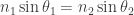
In this equation, “sin” represents the trigonometric sine function. The quantities 

The refractive index requires a bit of explanation. It represents (in a very specific sense) the fraction by which the speed of light is decreased in that particular medium. In other words, the speed of light in vacuum is 


For those who are not that comfortable with trigonometry, we can summarize the properties of Snell’s law in words. When a ray of light is travelling from a rarer to a denser medium, its direction gets bent towards the optical axis (the dashed perpendicular line). When a ray of light is travelling from a denser to a rarer medium, its direction gets bent away from the optical axis. We compare the two cases below.

You may notice the only difference between the two pictures is the direction of the arrows! This is an important observation: refraction is a reversible process! If a ray coming from a rare medium at angle
Snell’s law is named after the Dutch astronomer Willebrord Snellius (1580-1626), though it is now known that it was discovered much earlier: the first correct description seems to have been achieved by the Baghdad scientist Ibn Sahl (c. 940-1000), in his book On Burning Mirrors and Lenses, published in 984.
People probably had an intuitive understanding of refraction much, much earlier than this, however. Because light is refracted when it exits a body of water, things underwater appear to be in a different position than they actually are. Spear fishermen figured out long ago that one must strike at a spot closer than the fish appears in order to spear it.

So we now have a description, both mathematical and observational, of what refraction is, and the next natural question to ask is: why does it happen? We have mentioned that refraction occurs because the light changes speed as it passes the interface between two media; this is clear from Snell’s law itself, which depends on the refractive indices of the two media. It is not clear, however, how a change in speed can also result in a change of direction. After all, when I step on the brakes of my car, my car (hopefully) doesn’t go swerving off to the side!
The answer to this conundrum lies in the wave nature of light. Though in most ordinary circumstances one can visualize light as traveling along definite lines (rays), as we have shown in the pictures above, in reality light propagates as a wave which is spread out through space. A snapshot of what refraction looks like for a wave is shown below, with the ray direction drawn on top.

This picture assumes a plane wave coming from a rare medium from below and traveling into a denser medium like glass. The bright colors represent the peaks of the wave (to be referred to as the wavefronts), which the dark colors represent the troughs. It should be noted that the direction of propagation of the wave (indicated by the ray direction) is perpendicular to the wavefronts.
It should be noted that the wavelength (distance between wavefronts) gets smaller when the wave enters the dense medium. This is the natural result of the wave speed decreasing: just as the separation between cars gets smaller when the speed limit drops, the separation between wavefronts gets smaller when the wave speed drops.

The wave, however, must be continuous across the interface between the two media: the wavefronts must match up on either side of the interface, as they do in the picture above. Because the wavefront spacing is different on either side, the only way they can match up is if the wavefronts are tilted in the denser medium — the wave must change its direction of propagation! An animation of refraction in action is shown below.

This physical explanation may not seem entirely satisfactory — is there a simpler way to explain why the wave would change direction? To some degree we have to accept that refraction “is what it is”: not every physical phenomenon, even one as mathematically simple as refraction, can be explained in everyday terms. If we’re willing to be a little silly, however, we can come up with a crude analogy.
Let’s imagine a piece of wood sliding along a sheet of ice. This piece of wood might be a hockey stick dropped by a player who was checked into the boards particularly hard. As it travels, this piece of wood ends up crossing a “sticky” line, which might be a very poorly painted blue line at an ice rink. The starting situation is as follows.

So what happens when the stick starts to cross the blue line? The right side, which crosses first, slows down, but the left side keeps moving. The net result? The stick rotates as it crosses the line, and its direction of travel naturally must change along with it!

By the time the entire stick crosses the blue line, every part of it has been slowed equally. It is now moving along a straight path again, but in a different direction than it was to begin with, just like a light wave changes direction on crossing the boundary between two media.
The stick in this case is analogous to the wavefronts of light, and the blue line represents the interface between two optical media. Though this example is crude, it does highlight an important aspect of refraction: it only happens for “wide” objects, such as long sticks or spread-out wavefronts. A tiny marble rolling across the same blue line would slow down but its direction of travel would be unaffected. With this in mind, we can say that refraction is a natural consequence of the “spread-out” wave nature of light.
So now that we understand what refraction is, what can we do with it? Well, pretty much all of conventional lens optics — eye glasses, contact lenses, microscopes, cameras, telescopes, magnifying glasses — is based on refraction. Light passing through a simple convex lens, for instance, will be refracted at both surfaces. Parallel light rays coming through the lens will be bent to converge to a focal point; this is illustrated below.

We can also draw a picture to illustrate the behavior of the wavefronts of light on passing through a lens of this sort.

You might notice that I haven’t drawn the wavefronts all the way to the point where they would, presumably, converge at the focus. The wave behavior of light in the region of focus is actually quite complicated, in large part due to interference and diffraction effects that arise in that region.
There is one curious aspect of the theory of refraction that we should address before concluding. In going from a rare medium to a dense medium, the biggest angle 

The areas shaded in red represent all possible areas that the incident and transmitted rays can propagate. But now we have a problem: we have said that refraction is a reversible process, and of course we can send in a ray from the denser medium from any direction. What will happen to the ray pictured below?

The light coming in at this angle falls outside of Snell’s law, at least as we have described it so far. It turns out that the ray will be completely reflected at the interface, and no light will be transferred into the rarer medium! The angle
Though the proper description of the optics of fibers requires some sophisticated mathematics, we can understand it roughly as shown in the following picture.

Light enters the glass fiber from the left at such an angle that it suffers from total internal reflection every time it bounces off of the boundary of the fiber. Essentially no light can escape from the fiber due to refraction, though a significant amount will be absorbed by the glass itself.
There’s so much more we can say about refraction! For instance, certain materials exhibit what is known as double refraction (or birefringence), as exhibited by this piece of optical calcite (source Wikipedia):

For optical calcite, there are two refracted rays that are transmitted by the material, instead of one, producing a double image. One of the refracted rays is independent of the orientation of the crystal, while the other rotates its position with the crystal, as shown in the short video below.
Double refraction arises because the unusual atomic crystalline structure of calcite causes different polarizations of light to be refracted differently.
Another unusual and surprising refractive effect is the recently-proposed idea of negative refraction. In principle, it is possible to fabricate materials which have a negative refractive index; a light ray entering or exiting such a material would be refracted in a sense opposite to a normal material.

I’ve gone on far too long about refraction, but anyone interested in more discussion of negative refraction can refer to this earlier post of mine.
Refraction, though one of the oldest optical phenomena to be observe and quantified, possesses a surprising amount of complexity and subtlety to it! The same thing can be said for reflection… but I’ll defer that discussion for another post.


When I was in grade sic (I believe), the teacher told us to think of it as a column of soldiers marching along concrete toward a sandy beach. When they reach the sand, they cannot march as fast, and so each soldier slows down. If they approach the beach straight on, then they will continue to move in the same direction, but somewhat more slowly. If they approach at an angle, however, then those soldiers who reach the sand first will slow down first, and the trajectory of the column of soldiers will be changed.
I always found it a good way to think of refraction. The one thing I didn’t understand — and still don’t — is that if light slows down when entering the medium, does time also slow down?
Thanks for the comment! A collection of soldiers marching is a good way to think about it, though it actually is a little subtle — one has to assume that the later soldiers adjust their direction to stay in line with the slower soldiers, otherwise they end up traveling in their original direction but at a different angle.
Time is completely unaffected when light passes into a medium — in fact, refraction is derived from the wave theory of light by using the assumption that the frequency of wave oscillation does not change on passing into the medium. The idea that time is affected comes, I suspect, from thinking about the special theory of relativity. In special relativity, the speed of light is said to be the same for all observers… but this is in a vacuum, not in a medium! In matter, light can slow down pretty much the same way a car or any ordinary object can.
Pingback: Waves,Properties and Their Applications. « PhysicsRUs
If this is true then why do you not see light build up like water coming up to a dam?
Cliff – The reason that water builds up when it reaches a dam is due to the large mass associated with the wave. Because a light wave is essentially mass-less, you will not see a build up, however, the spacing between the wave fronts will be closer in the dense medium than they were outside the medium.
When the wave front hits the transparent medium, they will simply be slowed down. This should give the incoming waves the opportunity to “catch up”.
A dam may be more properly described as a reflective surface. When light hits a reflective surface, it will bounce back and lead to constructive and destructive interference. These interference patterns could be related to what you hope to see as a light “build up” effect.
very nice explanation.Dr.Nagaral Ashok Mahadevappa Professor Ophthalmology India