
This is the second in a series of posts about the upcoming OSA Frontiers in Optics meeting in Orlando. This post covers research related to the presentation FM3F.1: Alan E. Willner, Multiplexing Information-Carrying Orthogonal Beams using Orbital Angular Momentum States. To be (hopefully) cross-posted at the Frontiers in Optics blog.
Do you think your internet is too slow? If you’re like me, you probably do, even though the speed of data transmission has exploded over the past 15 years. When I was in graduate school, dial-up modems that could download 56 kbit/s (56 thousand bits per second) were state of the art, whereas today some broadband business connections* can download 400 Mbit/s (400 million bits per second)! But even still I want more data, and at a faster rate — and I’m not alone!
Fortunately, it is possible that the rate of telecommunications may increase dramatically in the near future. Over the past couple of years, researchers have demonstrated the possibility of transmitting data at a rate of over a terabit/second (one million million bits per second), in both free space** and an optical fiber***, by giving the light that carries the data a “twist” before transmission!
So what is this “twist,” and how does it allow us to increase the rate of data transmission? To understand this, we should first take a rough look at how we currently transmit data.
The most overt illustration of how information is transferred can be seen in commercial radio. Different radio stations broadcast at different frequencies: one of my twitter friends is a DJ at California’s Z-Rock FM, which broadcasts at a frequency of 106.7 MHz (106.7 million cycles/second). What, exactly, does this mean? It means that the broadcast antenna emits waves with a carrier frequency of 106.7 MHz, and that the audio signal is added to this carrier frequency as a variation of the frequency (frequency modulation). For AM (amplitude modulation) radio stations, the audio signal is encoded by varying the amplitude of the carrier frequency.
Humans can hear sounds up to a range of about 20 kHz (thousands of Hertz). Roughly speaking, this means that the actual radio signal has its frequency band broadened by about 20 kHz, and radio stations must have their carrier frequencies separated by at least this amount to avoid overlapping their broadcasts. As the designated FM radio frequency band is between 88 MHz and 108 MHz, only a finite number of stations can broadcast in the same area. Because radio signals decay as they travel, different cities can use the same frequencies; however, if you’ve ever traveled between two such cities, you know that in the “frontier” the stations can overlap.
What can we do if we want to transmit more data? One option is to broadcast using a higher carrier frequency. Today, our landline phone and internet data is transmitted using visible light, which has a frequency on the order of 
I’ve described the basics of fiber optics on this blog before. In short, a glass fiber can trap light traveling within it via the process of total internal reflection, and transmit it more or less cleanly through to the other side.

A ray of light bouncing in an optical fiber.
A single glass fiber can simultaneously trap light beams at many different frequencies, and therefore transmit a lot of information in parallel. However, as I have noted, our demand for fast information, and a lot of it, means that we are quickly filling the capacity of even these systems. Can we do even better?
One option that is already applied is to use the polarization of light to squeeze more information into a fiber. Light is a transverse electromagnetic wave (i.e. the field vibrates perpendicular to the direction of travel), and if you were able to see the individual oscillations of the electric field head-on, you would see that they come in two distinct varieties, horizontal and vertical.
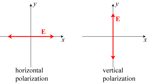
Horizontal and vertical polarization head-on. Of course, the field can oscillate along any direction, but any other direction can be written as a combination of these two. For instance, a “diagonal” polarization would be equal parts horizontal and vertical.
For each frequency of light, we can therefore send two simultaneous signals — one horizontally polarized, one vertically polarized — through the fiber and separate them at the receiver, as the two polarizations do not interfere with one another. Using polarization, we therefore can double the amount of information we transmit.
Can we go any further? If we use a thicker fiber (known as a multimode fiber), light can actually travel through the fiber over several independent paths; the light is said to travel over multiple spatial modes of the fiber, and in principle these modes can be extracted again. If we could send even three of these modes simultaneously, we could multiply our data transmission rate by another factor of 3, a huge improvement!

A hypothetical three-mode fiber, with light traveling via several different paths through the system. Colors only used for clarity; the beams are in principle the same wavelength.
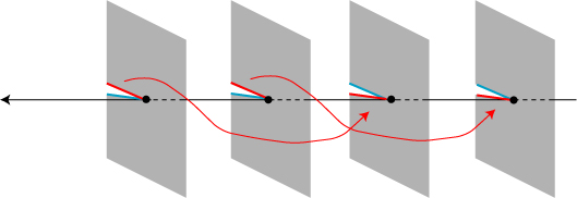
In general, however, these spatial modes tend to mix in a multi-mode fiber, so that the output is very much like the “frontier” radio signals discussed earlier. Light sent in through mode 0 might come out in a combination of modes 0, 1 and 2, with similar results for the other modes, and the information is scrambled and error-prone.
However, there are a special set of spatial modes that are significantly resistant to scrambling: the set of so-called vortex or angular momentum modes!
To properly understand what a vortex beam of light looks like, we should first look at an ordinary, “plane,” wave of light. Like all waves, it consists of a series of semi-regular ups-and-downs spread out through space. For a plane wave, the sequence of “ups” form a series of planes in space that we call wavefronts, as illustrated below.

Illustration of the wavefronts of a plane wave. The “ups” of the wave, which form planes, are traveling to the left.
For this plane wave, the wavefronts are all parallel to each other and never touch one another. In fact, for most light waves, this is a very good approximation of what the wave looks like if you were to zoom in and magnify it almost anywhere (zoom in a lot — the wavefronts are spaced by roughly 500 billionths of a meter).
But let’s suppose that we slice each of the wavefronts from their middle out to their edge (at infinity), and join the edges together as illustrated below:
Joining tears in wavefronts together.
What we end up with in the end is a spiral wavefront!
A spiral, or helical, wavefront.
As this wave propagates to the left, the wavefronts still advance: the net effect is that the whole structure twists like a screw or a drill bit! This is now a vortex wave, so named because the wavefronts swirl around the central axis somewhat akin to water swirling around a drain.
In the picture above, each wavefront is tied directly to the wavefront before or after it. However, we can create an entire, in principle infinite, set of different twisted waves by tying different rips together. For instance, the next most complicated situation is to tie every other wavefront together, as shown below.
Creating a second-order vortex.
This gives us a pair of entwined helical wavefronts, a structure distinct from the previous one.

A second-order vortex, consisting of a pair of entwined helices.
We can go even further, tying wavefronts separated by 3 to make a third-order vortex, or by 4 to make a fourth-order vortex, and so forth. We can also go the other way and reverse the joined of the blue and red lines in our first “tear” picture to make a vortex that twists the other way, a vortex of order -1. In the end, it is (in principle) possible to make an infinite family of wavefields, each with its own distinct twist, labeled by an integer value. (I talk a bit more about vortex beams in an earlier blog post, for those interested.)
So how does this help us in communication? Because the wavefronts effectively spin as they travel, they actually carry angular momentum — momentum of rotation! And much like a spinning bicycle wheel resists falling over, a vortex light beam has a built-in resistance to having its angular momentum changed. Each vortex mode, with its own integer twist value, can be propagated over appreciable distances in a fiber or through the air and maintain its identity.
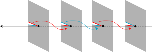
This is precisely what researchers have now tested experimentally. In the fiber optics experiment***, they designed a special optical fiber of 1.1 km length that minimizes any possible coupling between vortex modes. They then performed two experiments: they sent four different modes at a single frequency through the fiber and sent 2 different modes at 10 distinct frequencies through the fiber. The former case is crudely illustrated below.

Data was encoded into four different states. Two of these were given no twist at all, but were given opposite forms of circular polarization. The other two states were given opposite twists and polarization. The fields were combined and sent into an optical fiber, and separated out (“demultiplexed”) at the output.
The result? In the former case, they achieved 400 gigabits/second data transmission, and in the latter an impressive 1.6 terabits/second, and both results conformed to limits required for essentially error-free communication.
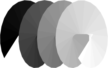
The year before, many of the same researchers had collaborated on sending data through vortex beams in free-space propagation rather than a fiber. Propagation of light through free-space carries its own challenges, namely in the degradation of waves by atmospheric turbulence. An extreme example of this is the “heat shimmer” one sees in distant images on very hot days, as shown below.

Heat shimmer, a distortion of optical images by atmospheric turbulence.
Fortunately, earlier theoretical research (my own, in fact****) has demonstrated that vortex beams are somewhat resistant to atmospheric influences over several kilometers, though some “cross-talk” will inevitably occur between modes.
The recent research worked with a more modest goal, propagating the field only 1 meter through the air! However, they were able to transmit data using four angular momentum states (twist +4, +8, -8, and +16) and achieved an impressive data rate of 1.37 terabits/second.
Will vortex beams form the basis of a new telecommunications revolution? It is perhaps to early to say, as there are a lot of practical questions to be answered, such as whether the method is cost-effective and whether it is resistant to all sort of “in the field” complications that don’t arise in the laboratory. Furthermore, last year a simple experiment of this sort sparked a rather heated argument between scientists and engineers on whether this is even a novel technique! (I’ll have to leave discussion of that fun argument for another post.)
However, the results looks promising so far, and at the very least they put a new “twist” into optical research!
*******
* Of course, most of us at home in the U.S. have a relatively paltry connection speed of 15 Mbit/s, at best.
** Wang, Yang, Fazal, Ahmed, Yan, Huang, Ren, Yue, Dolinar, Tur and Willner, “Terabit free-space data transmission employing orbital angular momentum multiplexing,” Nature Photonics 6 (2012), 488-496.
*** Bozinovic, Yue, Ren, Tur, Kristensen, Huang, Willner, Ramachandran, “Terabit-scale orbital angular momentum mode division multiplexing in fibers,” Science 340 (2013), 1545-1548.
**** G. Gbur and R.K. Tyson, “Vortex beam propagation through atmospheric turbulence and topological charge conservation,” J. Opt. Soc. Am. A 25 (2008), 225.


