
There has been a lot of excitement among researchers about the science of invisibility over the past decade, and a variety of designs of invisibility cloaks have been suggested since the groundbreaking 2006 papers. I’ve talked a lot about invisibility on this blog, but I haven’t said a lot about one of the most intriguing — and overlooked — possibilities: the use of cloaking to protect objects, instead of just hide them!
What do I mean? Well, an invisibility cloak is, in principle*, a material structure that guides light around a central space — the cloaked region — and sends it on its way as if it had hit nothing at all. An illustration of how this would work for light rays, from the original paper by Pendry, Schurig and Smith, is shown below.
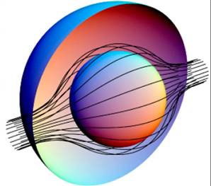
The black lines represent the light rays, being bent around the cloaked region (inner sphere). Such a cloak, however, is not limited to rays of light; it has been demonstrated that it guides waves of light perfectly, as well.
But if a cloak can be designed to deflect light waves, it stands to reason, then why not other types of waves, or fields? Magnetic fields could be deflected, to protect sensitive electronics within. Water waves could be deflected, to protect offshore platforms or buoys from damaging waves during extreme storms. Or, maybe — just maybe — seismic waves from earthquakes could be guided around vulnerable buildings!
Recent research* suggests that protecting buildings from earthquakes might be possible, at least to a limited extent. In experimental work published in April of this year, French researchers were able to screen, or protect, a region of earth from artificially generated seismic waves.
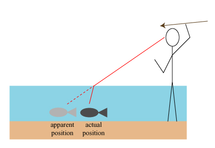
In order to put the French research in its proper context, we should say a little first about how optical cloaks work. Though there is much we can say about the optics of a cloaking device, at its heart is the phenomenon of refraction, in which a light wave changes its direction when passing between media of different optical properties. In short, when light goes from an optically rare medium, like air, to an optically “dense” medium, like water, it slows down. When it hits the boundary between these two media at an angle, this change in speed results in a change of direction. As a practical example, refraction requires spear-fishers to aim for a spot closer than the fish appears to be.
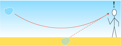
At sharp boundaries between materials, light makes a sharp change of direction; when the material properties change more gradually, however, the path of light can be made to curve gradually. Most of us have seen this before, in the form of a mirage! When the ground is extremely hot (sand, pavement), the temperature at ground level is hotter than right above. This results in the air being gradually more optically dense as one goes higher up. Light from the blue sky that would normally hit the ground instead curves upward to our eyes, making it appear that there is blue stuff (water?) on the ground.
This curving of light by using gradient materials is, in essence, how optical cloaks work. By choosing an appropriate material structure in which the optical properties vary continuously, light can be guided around the central cloak region and sent along their way.
This same idea can be applied to any sort of wave, as long as one has a way to continuously change the speed of waves in question. The first theoretical attempts to design cloaks for seismic waves were introduced in 2012 by researchers from Manchester and Rutgers**. Though the papers did not explicitly discuss seismic waves, the implications were obvious and noted in press accounts at the time.
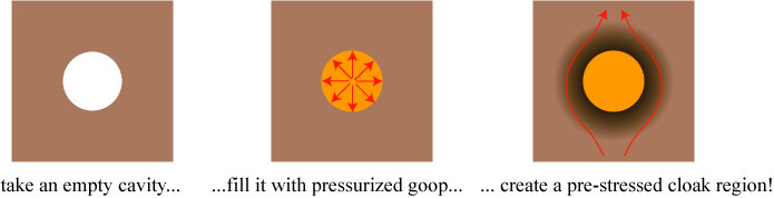
To change the speed of seismic waves, one needs to either change the material that the waves are traveling through or change the density of the material. For the 2012 papers, the authors went the latter route, using a clever idea, as follows. Imagine that we have a homogeneous material with a cylindrical hole in it. Now we fill the hole with a fluid, but we force it in so much that it applies a large pressure to the boundary of the hole. This pressure will push the boundary material outward, creating a region with different density. The researchers demonstrated mathematically that this “pre-stressed” region already acts like a cloaking device for seismic waves.
One likes to think that this could be done to protect buildings from earthquakes — create a pre-stressed region around the foundation of a building and, hopefully, a large fraction of damaging seismic waves will pass around the building.
But this scheme of cloaking raises an interesting problem that is more political than scientific: if you guide earthquake waves around your building, then they can hit the building behind yours! Are you now liable for the destruction that would not have happened without the cloak?
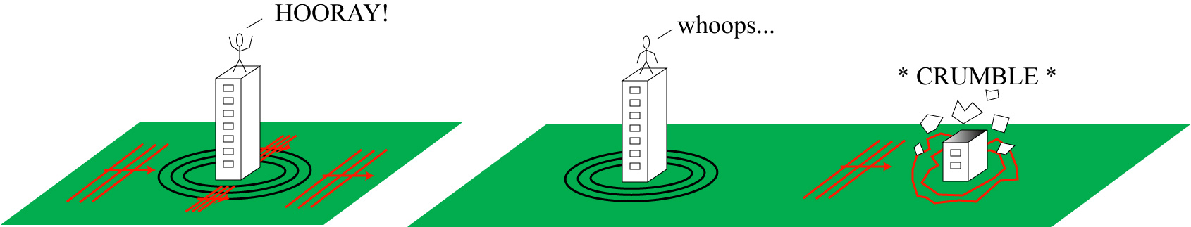
With this in mind, it becomes clear that cloaking — guiding the waves around the central region and sending them along their original path undisturbed — is really more than we need to protect objects from seismic waves. All we really want to do is keep the seismic waves from hitting the building; if they get scattered in all directions or dissipated harmlessly into other forms of energy, so much the better.
This alternate approach was first considered in 2012 by Korean and Australian researchers***, who suggested that it should be possible to create a so-called “stop band” for seismic waves in a region around a building that will simply block or absorb the waves; a similar idea is what was tested experimentally by the French research team and reported on this year.
So what is a “stop band?” The term refers to a range of frequencies (a “band”) which cannot propagate in the material in question (they are “stopped”). There are several ways of creating a stop band****; we will focus on the one used by the French research team, which employs wave interference effects.
To see how this works, let’s imagine a light wave traveling to the right in a thick piece of glass. Along the way, the wave encounters a pair of extremely thin slabs of a different glass material, as illustrated below.
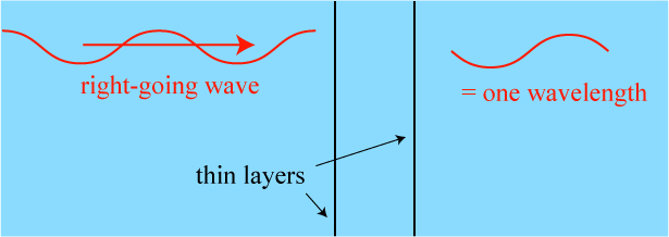
So what happens? Well, some light will inevitably be reflected at each of the thin layers; it would be reasonable to expect that more light will be reflected by two layers than a single layer.
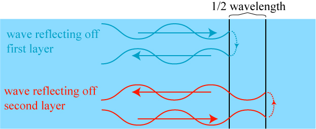
But that is not necessarily true! If the layers are separated by one quarter of a wavelength, the waves reflected by the first layer and the second layer will partially cancel out, meaning that less light is reflected by two layers than one layer! The “ups” of the one reflected wave cancel with the “downs” of the other reflected wave, leading to less reflection.

This is, in fact, the basis of anti-reflection coatings that are placed on optics such as eyeglasses and camera lenses; a thin film of material is deposited on the glass surface, and the top and bottom of this film acts as the two layers in our example.
For our purposes, though, we consider another case: if the layers are separated by half a wavelength, then the waves reflected off of the two layers will constructively interfere: the ups of one wave will combine with the ups of the other, resulting in a bigger reflected wave and an overall greater reflection than one would expect!
As you might imagine, this only works well when the layers are separated exactly by 1/2 a wavelength. However, if we line up a large number of layers, all spaced by 1/2 a wavelength, a strange thing happens: a range of wavelengths around the “special” wavelength all begin to be perfectly reflected. This multilayer structure has generated a photonic bandgap, that blocks a large range of wavelengths (or frequencies) of light.
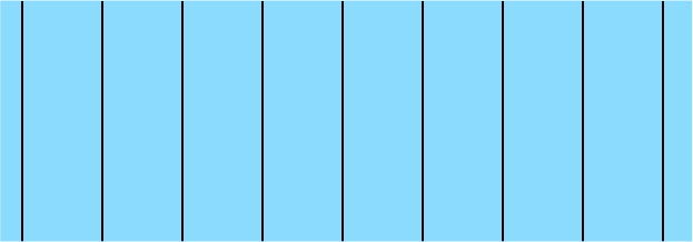
With a lot of layers, our structure will perfectly block a range of frequencies, not just one.
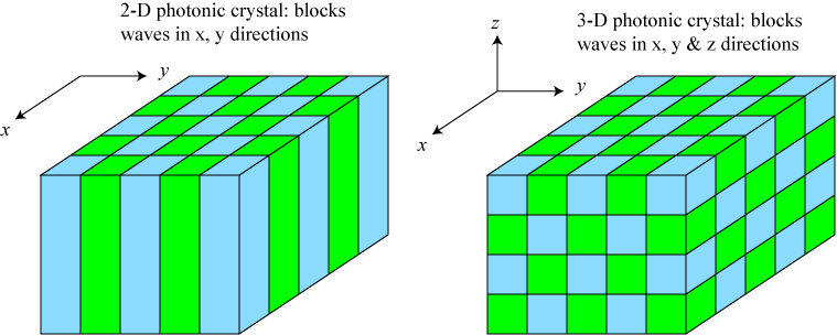
This structure will only block waves traveling along one axis, however: namely, the horizontal axis. It won’t, therefore, block waves that are traveling upwards in the picture, or waves that are traveling into the page, assuming a three-dimensional structure. However, if we make a two-dimensional periodic structure, we can block waves that lie within a plane; if we make a three-dimensional periodic structure, we can block waves from traveling anywhere within a volume. In optics, because of the repeating structure, these devices are known as photonic crystals.
Just as we can design a cloaking device for any sort of wave, we can design a “photonic” crystal for any type of wave, as well. This brings us back to the experiment of the French research team. They created a seismic bandgap by drilling a periodic array of boreholes into the ground, as the photograph below illustrates.

Photograph of the experimental setup, taken from S. Brûlé, E.H. Javelaud, S. Enoch and S. Guenneau under Creative Commons 3.0.
The mechanical source produced shallow seismic waves with a wavelength of 1.56 meters, comparable to the 1.73 meter separation between the centers of the boreholes, suggesting that the boreholes should produce at least a partial seismic bandgap.
So what did the researchers observe? The main experimental result, showing the amplitude of the waves throughout the plane of the experiment, is shown below.
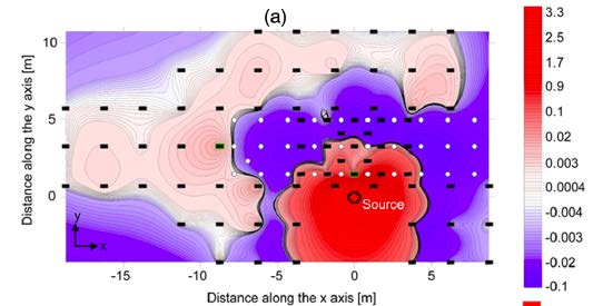
Amplitude of seismic waves in experiment, taken from S. Brûlé, E.H. Javelaud, S. Enoch and S. Guenneau under Creative Commons 3.0. In the figure, the circles indicate the holes, while the black rectangles indicate sensors.
As one can see from the figure, in the region of the holes, there is little to no amplitude from the seismic waves, as compared to the regions without the holes to the side and behind. It appears that the seismic waves have been impeded by the presence of the boreholes, as predicted by the theoretical model.
It is unclear to me (especially not knowing much about seismology) how applicable these results are to real earthquake conditions. It is my understanding that earthquakes produce a broad range of wavelengths, from meters to hundreds of meters, and that these waves are of different form — longitudinal and transverse — and can travel at different depths. However, even a partial shielding of seismic waves could potentially be beneficial, as anything reducing the strength of waves hitting a structure essentially make the building more resistant to damage.
In any case, I love this experiment because it highlights the idea that developments in optical cloaking potentially have broader and farther-reaching implications than simply hiding from something.
*****************
* S. Brûlé, E.H. Javelaud, S. Enoch and S. Guenneau, “Experiments on Seismic Metamaterials: Molding Surface Waves,” Phys. Rev. Lett. 112 (2014), 133901. Free to read online!
** W.J. Parnell, Nonlinear pre-stress for cloaking from antiplane elastic waves,” Proc. Roy. Soc. A 468 (2012), 563-580, and A.N. Norris and W.J. Parnell, “Hyperelastic cloaking theory: transformation elasticity with pre-stressed solids,” Proc. Roy. Soc. A 468 (2012), 2881-2903.
*** S-H. Kim and M.P. Das, “Seismic waveguide of metamaterials,” Mod. Phys. Lett. B 26 (2012), 1250105.
**** For those interested in the technical details, I should note that the stop bands envisioned by the two research teams work in significantly different ways. Kim and Das’ technique uses subwavelength structures underground to create a metamaterial region where waves simply cannot propagate; the French team uses wavelength-size structures to create the seismic version of a photonic band gap.


Thanks for this post. Seems like there’s always something new I learn even after being in the field for 25 years…
Liked your article. Seems that this might have military applications. What about protection of buildings and other objects (vehicles) from shock waves caused by bomb blasts? I’m not a scientist. I’m just imagining possibilities.